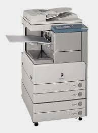
Canon ir105 service manual
Bagi yang membutuhkan panduan servis canon ir105, silahkan download pada link yang ada pada posting ini.
sebelum ke link download, silahkan lihat daftar isi / table off content dibawah ini.
Canon ir105 service manual/panduan servis ir105 ini berisi:
 CHAPTER 1 INTRODUCTION
1 Features
1.1 High Speed, High Quality
1.2 High Durability,High Reliability
1.3 High-Performance Controller,Large-Capacity Hard
1.4 Ease of Operation
1.5 Large-Capacity Paper Source
1.6 Various Delivery Processing (with options)
1.7 High-Level Printer Functions to
Support Networking
Requirements
2 Specifications
2.1 Copier
2.1.1 Type
2.1.2 System
2.1.3 Functions
2.1.4 Others
2.2 Side Paper Deck-N1
3 Names of Parts
3.1 External View
3.2 Cross Section
4 Operation
4.1 Power Switch
4.2 Control Panel
4.3 Extension Mode Items
4.4 User Mode
CHAPTER 2 NEW FUNCTION
1 Basic Construction
1.1 Outline of the Basic Construction
1.2 Wiring Diagram of the Major PCBs
2 Original Exposure System
2.1 Outline of the Original Exposure System
2.2 Changes Made to the Original Exposure System
2.3 Enlargement/Reduction
2.4 Preventing Overheating of the Scanner Motor
2.5 Arrangement of PCBs
2.6 Stabilizing the Scanning Lamp
2.7 Detecting the State (open/closed) of the ADF2.8 Detecting Dust in Stream Reading
2.9 Disassembly/Assembly
2.9.1 No. 1 Mirror Base Assembly
2.9.2 Scanner Drive Assembly
2.9.3 PCBs
2.9.4 Others
3 Image Processing System
3.1 Outline of the Image Processing System
3.2 Changes Made to the Image Processing System
3.3 4-Channel High-Speed Reading CCD
3.4 CCD Adjustment
3.5 Analog Image Processing
3.6 Digital Image Processing
3.7 Detecting the Orientation of Originals
3.8 Disassembly/Assembly
3.8.1 CCD Unit
3.8.2 Hard Disk
4 Laser Exposure System
4.1 Outline of the Laser Exposure System
4.2 Changes Made to the Laser Exposure System
CONTENTS
4.3 Disassembly/Assembly
4.3.1 Laser Unit
4.3.2 BD Unit
5 Image Formation System
5.1 Outline of the Image Formation System
5.2 Changes Made to the Image Formation System
5.3 Addition of the Pre-Transfer Exposure LED
5.4 Measures Against Overheating of the Developing Unit
5.5 Addition of the Developing Fan
5.6 Modifying the Developing Cylinder Cover 3
5.7 Preventing Adhesion of Toner to the Cleaning Blade
5.8 Disassembly/Assembly
5.8.1 Process Unit
5.8.2 Drum Cleaner Unit
5.8.3 Charging Wires
5.8.4 Area Around the Process Unit
6 Pickup/Feeding System
6.1 Outline of the Pickup/Feeding System
6.2 Changes Made to the Pickup/Feeding System
6.3 Optical Sensors
6.4 Image Write Start Sensor
6.5 Index Paper Attachment
6.6 Disassembly/Assembly
6.6.1 Manual Feed Tray Assembly
6.6.2 Cassette Pickup Assembly
6.6.3 Vertical Path Roller Assembly
6.6.4 Registration Feed Assembly
6.6.5 Duplex Unit
6.6.6 Others
7 Fixing System
7.1 Outline of the Fixing System
7.2 Changes Made to the Fixing System
7.3 Fixing Temperature Control
7.4 Transparency Mode
7.5 Thick Paper Mode
7.6 Power Save Mode
7.7 Detecting an Error
7.8 Down Sequence Control
7.9 Disassembly/Assembly
7.9.1 Fixing Heater and the Control Parts
7.9.2 Fixing Roller Assembly
7.9.3 Delivery Assembly
7.9.4 Paper Sensors
8 Externals/Auxiliary Controls
8.1 Changes Made to Externals/Auxiliary Controls
8.2 Fans
8.3 Sequence of Fan Operation
8.4 Disassembly/Assembly
8.4.1 External Covers
8.4.2 Control Panel
8.4.3 Fans
8.4.4 Drive Assembly
8.4.5 Switches
8.4.6 PCBs
8.4.7 Others
9 Side Paper Deck-N1 .................
9.1 Outline of the Side Paper Deck
9.2 Changes made to the Side Paper Deck
9.3 Optical Sensors
9.4 Disassembly/Assembly
9.4.1 Removing the Deck Pickup Sensor Unit
9.4.2 Removing the Deck Feed Sensor Unit
CONTENTS
CHAPTER 3 MAIN CONTROLLER
1 Basic Operation
1.1 Functional Construction
1.2 Outline of the Electrical Circuitry
1.2.1 Outline
1.2.2 Main Controller PCB
1.2.3 Hard Disk Drive
1.3 Start-Up Sequence
1.3.1 Outline
1.3.2 Start-Up Sequence
1.3.3 Construction of the System Software
1.4 Inputs/Outputs the Major PCBs
1.4.1 Connection Diagram of the Major PCBs
2 Digital Image Processing
2.1 Outline
2.2 Input Image Processing
2.2.1 Image Data from the Reader Unit
2.2.2 Enlargement/Reduction (main scanning direction)
2.2.3 Edge Emphasis
2.2.4 Edit Processing
2.2.5 Density Conversion (LUT)
2.2.6 Binary Processing (error diffusion method T-BIC)
2.2.7 Binary (dither screen method)
2.3 Controlling the Image Memory
2.3.1 Compression/Expansion, Rotation, and Enlargement/Reduction
2.3.2 SDRAM
2.4 Output Image Processing
2.4.1 Smoothing
2.4.2 Thickening (PDL output only)
2.4.3 Binary-Binary Conversion (read image output only)
3 Soft Counters
4 Controlling the Power Supply
4.1 Outline
4.2 Power Supply Mode
4.3 Standby Mode (normal operation)
4.4 Power Save Mode
4.5 Low Power Mode
4.5.1 Shift from Standby Mode (standby ® low power)
4.5.2 Shift to Standby Mode (low power ® standby)
4.6 Sleep Mode
4.6.1 Shift from Standby Mode (standby ® sleep)
4.6.2 Shift from Low-Power Mode (low power® sleep)
4.6.3 Return to Standby Mode (sleep ® standby)
4.7 OFF Mode
4.7.1 Shift from Standby Mode (standby ® OFF mode)
4.7.2 Shift from Low-Power Mode (low-power® OFF mode)
4.7.3 Return to Standby Mode (OFF mode ® standby)
4.8 Power Supply OFF Mode
CONTENTS
CHAPTER 4 INSTALLATION
1 Selecting the Site
2 Unpacking and Installation
2.1 Points to Note Before Starting the Work
2.1.1 Attachments
2.2 Unpacking
2.3 Mounting the Scanner
2.4 Installing the Fixing Assembly
2.5 Mounting the Charging Assemblies
2.6 Checking the Developing Assembly
2.7 Mounting the Pickup Assembly
2.8 Mounting the Control Panel
2.9 Supplying the Toner
2.10 Mounting the ADF
2.11 Cassette
2.12 Index Paper Attachment
2.13 Attaching the Labels, Setting Paper, Checking Images/Operations, and User Mode
2.14 Changing the Paper Size for the Front Deck (right, left)
3 Relocating the Machine
4 Installing the Card Reader-D1
4.1 Installing the Card Reader-D1
5 Installing the NE Controller-A1/NE Controller-B1/Copy DataController-A1
5.1 Installing the NE Controller-A1/
NE Controller-B1/Copy Data
Controller-A1
CHAPTER 5 MAINTENANCE AND INSPECTION
1 Periodically Replaced Parts
2 Guide to Replacement of Durables
2.1 Copier
2.2 Side Paper Deck
3 Scheduled Service Chart
4 Scheduled Service Items
4.1 Copier
4.2 Scheduled Service Work
4.2.1 Work 1
4.2.2 Work 2
CHAPTER 6 TROUBLESHOOTING
1 Guide to the Troubleshooting Tables
1.1 Image Adjustment Basic Procedure
1.1.1 Making Pre-Checks
1.1.2 Making Checks on the Printer Side (1/2)
1.1.3 Making Checks on the Printer Side (2/2)
1.1.4 Making Checks on the Scanner Side
2 Standards and Adjustments
2.1 Image Adjustment-Related Items
2.1.1 Adjusting the Image Position for Printer Output
2.1.2 Adjusting the Image Position of Copier Output (book mode)
2.1.3 Adjusting the Image Position of Copier Output (ADF mode)
2.2 Scanning System
2.2.1 Replacing the Scanner Drive Cable
2.2.2 Adjusting the Scanner Mirror Base
CONTENTS
2.2.3 When Replacing
the Standard White Plate
2.2.4 When Replacing
the Scanning Lamp
2.3 Image Formation System
2.3.1 Stringing the Grid Wire of the Primary Charging Assembly
2.3.2 Stringing the Charging Wire of the Charging Assemblies
2.3.3 Mounting the Drum
Cleaning Blade
2.4 Pickup/Feeding System
2.4.1 Orientation of the Deck/Cassette Pickup Roller
2.4.2 Orientation of the Deck/Cassette Separation Roller
2.4.3 Orientation of the Feeding Roller of the Deck/Cassette Pickup Assembly
2.4.4 Orientation of the Pickup Roller of the Manual Feed Tray/Side Paper Deck
2.4.5 Orientation of the Feeding Roller of the Manual Feed Tray
2.4.6 Orientation of the Feeding Roller of the Side Paper Deck
2.4.7 Adjusting the Pressure of the Deck/Cassette Separation Roller
2.4.8 Adjusting the Pressure of the Pickup/Feeding Roller of the Manual Feed Tray
2.4.9 Locations of the Solenoid
2.4.10 Location of the Fixing Web Solenoid (SL2)
2.4.11 Position of the Delivery Flapper Solenoid (SL3)
2.4.12 Position the Fixing/Feeder Unit Locking Solenoid (SL4)
2.4.13 Position of the Multifeeder Latch Solenoid (SL6)
2.4.14 Position of the Deck (right) Pickup Solenoid (SL7)
2.4.15 Position of the Deck (Left) Pickup Solenoid (SL8)
2.4.16 Position of the Cassette ¾ Pickup Solenoid (SL9/10)
2.4.17 Position of the Side Paper Deck Pickup Roller Releasing Solenoid
2.4.18 Fitting the Side Guide Timing Belt of the Manual Feed Tray Assembly
2.4.19 Fitting the Drive Belt
2.5 Fixing System
2.5.1 Points to Note When Mounting the Fixing Heater
2.5.2 Adjusting the Lower Roller Pressure (nip)
2.6 Laser Exposure System
2.6.1 When Replacing the Laser Unit
2.6.2 Checking the Laser Power
2.7 Electrical Parts-Related Items
2.7.1 Electrical Parts Requiring Work After Replacement
2.7.2 When Replacing the Scanning Lamp
2.7.3 When Replacing the CCD Unit
2.7.4 When Replacing Reader Controller PCB
2.7.5 When Replacing the Main Controller PCB
CONTENTS
2.7.6 When Replacing the HDD Unit
2.7.7 When Replacing the DC Controller PCB
2.7.8 When Replacing the HV-DC PCB
2.7.9 When Replacing the Laser Unit
2.7.10 When Replacing the Potential Sensor/Potential Control PCB
2.7.11 Checking the Surface Potential Control System
2.8 Potential Control System Conversion Table
2.9 Checking the Environment Sensor
2.10 Checking the Photointerrupters
2.11 Checking the Optical Sensors
3 Troubleshooting Image Faults
3.1 Making Initial Checks
3.1.1 Checking the Side of Installation
3.1.2 Checking the Originals
3.1.3 Checking the Copyboard,.Cover, Copyboard Glass, and Standard White Plate
3.1.4 Checking the Charging Assemblies
3.1.5 Checking the Developing Assembly
3.1.6 Checking the Paper
3.1.7 Checking the Periodically Replaced Parts
3.1.8 Others
3.2 Sample Faulty Images
3.3 Troubleshooting Image Faults
3.3.1 The output is too light (halftone area)
3.3.2 The output is too light (solid black area)
3.3.3 The output is too light (overall, considerably)
3.3.4 The output has uneven density(darker at the front)
3.3.5 The output has uneven density (lighter at the front)
3.3.6 The output is foggy (overall)
3.3.7 The output has vertical fogging
3.3.8 The output has black lines (vertical, fuzzy, thick)
3.3.9 The output has black lines (vertical, fine)
3.3.10 The output has white spots (vertical)
3.3.11 The output has white lines (vertical)
3.3.12 The output has white spots (horizontal)
3.3.13 The back of the output is soiled
3.3.14 The output has a fixing fault
3.3.15 The output has a displaced leading edge (considerably large margin)
3.3.16 The output has a displaced leading edge (large margin)
3.3.17 The output has a displaced leading edge (no margin)
3.3.18 The output is blurred
3.3.19 The output has horizontal fogging
3.3.20 The output has poor sharpness
3.3.21 The output is solid blank
3.3.22 The output is solid black
CONTENTS
4 Troubleshooting Malfunctions
4.1 Troubleshooting by Malfunction
4.1.1 E000
4.1.2 E001
4.1.3 E002
4.1.4 E003
4.1.5 E004
4.1.6 E005
4.1.7 E010
4.1.8 E012
4.1.9 E013
4.1.10 E014
4.1.11 E015
4.1.12 E019
4.1.13 E020
4.1.14 E025
4.1.15 E032
4.1.16 E043
4.1.17 E051
4.1.18 E065
4.1.19 E067
4.1.20 E068
4.1.21 E069
4.1.22 E100
4.1.23 E110
4.1.24 E111
4.1.25 E121-0001
4.1.26 E121-0002
4.1.27 E202 (The keys in the control panel are locked.)
4.1.28 E204 (The keys in the control panel are locked.)
4.1.29 E211
4.1.30 E215
4.1.31 E218
4.1.32 E219
4.1.33 E220
4.1.34 E222
4.1.35 E226
4.1.36 E240
4.1.37 E241
4.1.38 E243
4.1.39 E251
4.1.40 E302
4.1.41 E315
4.1.42 E320
4.1.43 E400
4.1.44 E402
4.1.45 E404
4.1.46 E405
4.1.47 E410
4.1.48 E422
4.1.49 E601
4.1.50 E602
4.1.51 E676
4.1.52 E677
4.1.53 E710-0001 (reader controller), E710-002
(DC controller), E710-0003 (main controller)
4.1.54 E711-0001 (reader controller), E711-0002 (DC controller), E711-0003 (main controller)
4.1.55 E712
4.1.56 E713
4.1.57 E717
4.1.58 E732
4.1.59 E733
4.1.60 E737
4.1.61 E740
4.1.62 E741
4.1.63 E744
4.1.64 E800
4.1.65 E804
4.1.66 E805
4.1.67 E820
4.1.68 E823
4.1.69 E824
4.1.70 E830
4.1.71 AC power is absent
4.1.72 The DC power supply fails to operate.
4.1.73 Pickup fails
CONTENTS
4.1.74 The lifter fails to move up
4.1.75 The lifter fails to move up (pickup from cassette)
4.1.76 Pickup fails (multifeeder)
4.1.77 The vertical path roller fails to rotate
4.1.78 The registration roller fails to rotate
4.1.79 The No. 1 mirror base fails to move
4.1.80 The pre-exposure lamp fails to go ON
4.1.81 The scanning lamp fails to go ON
4.1.82 The toner feed motor (M6) inside the cartridge fails to operate
4.1.83 The feed motor (M18) inside the hopper fails to operate
4.1.84 The drum heater fails to operate
4.1.85 The Add Toner message fails to go ON
4.1.86 The Add Toner message fails to go ON
4.1.87 The Set Card Reader message fails to go ON
4.1.88 The Set Control Card message fails to go OFF
4.1.89 The Add Paper message fails to go OFF (deck light/left)
4.1.90 The Add Paper message fails to go OFF (cassette 3/4)
4.1.91 The fixing heater fails to operate
4.1.92 Pickup fails (side paper deck)
4.1.93 The deck lifter fails to move up (side paper deck)
5 Troubleshooting Feeding Problems
5.1 Copy Paper Jams
5.1.1 Pickup Assembly
5.1.2 Separation/Feeding Assembly
5.1.3 Fixing Assembly,
Delivery Assembly
5.1.4 Fixing assembly, Delivery assembly (reversal delivery assembly)
5.1.5 Cleaner assembly
5.1.6 Lower Feeding Assembly
5.2 Feeding Faults
5.2.1 Double Feeding
5.2.2 Wrinkles
6 Arrangement and Function of Electrical Parts
6.1 Clutches
6.2 Solenoids
6.3 Motors
6.4 Fans
6.5 Sensor 1
6.6 Sensor 2
6.7 Switches
6.8 Counters, There, Fuses, and Others
6.9 PCBs
6.10 Side Paper Deck-N1
6.11 Variable Resistors (VR), Light-Emitting Diodes (LED), and Check Pins by PCB
6.11.1 Main Controller PCB
6.11.2 Reader Controller PCB
6.11.3 DC controller PCB
6.11.4 HV-DC PCB
7 Upgrading
7.1 Outline
CONTENTS
7.1.1 Download Mode
7.1.2 Making Pre-Checks
7.2 Data Control
7.3 Downloading the System Software, RUI, and Language Module
7.3.1 Making Connections
7.3.2 Downloading
7.3.3 After Downloading
7.4 Upgrading the BOOT ROM
7.4.1 Making Preparations
7.4.2 Connection
7.4.3 Preparing BOOT ROM
7.4.4 After Downloading
7.5 Formatting the HDD
7.5.1 Making Connections
7.5.2 Starting Formatting
7.5.3 Points to Note When Formatting the Hard Disk
7.6 Upgrading by Replacing the DIMM/ROM
8 Backing Up Data
8.1 Outline
8.2 Backing Up Data
8.2.1 Making Preparations
8.2.2 Making Connections
8.2.3 Backing Up Data
8.2.4 Downloading Backup Data
8.2.5 Managing Backup Data
ERROR CODE
1 Error Codes
APPENDIX
1 GENERAL TIMING CHART
2 LIST OF SIGNALS/ ABBREVIATIONS
3 GENERAL CIRCUIT DIAGRAM
4 Special Tools Table
5 Solvents/Oils
SERVICE MODE
1 Construction of Service Mode
1.1 Outline
1.2 Starting Service Mode and Making Selections
1.3 Ending Service Mode
1.4 Backing Up Service Mode Settings
1.5 Using Service Mode .....
1.5.1 Initial Screen
1.5.2 Level 1/2 Screen
1.5.3 Level 3 Screen
2 COPIER
2.1 DISPLAY
2.2 I/O
2.3 ADJUST
2.4 FUNCTION
2.5 OPTION
2.6 TEST
2.7 COUNTER
3 FEEDER
3.1 DISPLAY
3.2 ADJUST
3.3 FUNCTION
3.4 OPTION
4 SORTER
4.1 ADJUST
4.2 OPTION
5 BOARD
5.1 OPTION
1.1 Outline of Error Codes
SILAHKAN DOWNLOAD PADA GAMBAR IR105 SERVICE MANUAL DIBAWAH INI
 Canon ir105 service manual